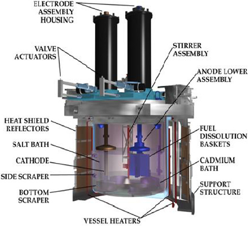
Conceptual diagram of an electrorefiner at the Argonne Lab circa 1999
| Home | Energy | Nuclear | Electricity | Climate Change | Lighting Control | Contacts | Links |
|---|
INTRODUCTION:
This web page sets out details of reprocessing of used CANDU reactor fuel to make Fast Neutron Reactor (FNR) fuel and reprocessing of FNR fuel. For an overview of the Ottensmeyer Plan please review OTTENSMEYER PLAN. The advantages of the Ottensmeyer Plan are the highest possible efficiency of usage of natural uranium for displacement of fossil fuels and near total elimination of long lived radio isotopes from the used nuclear fuel waste. That performance is achieved by taking advantage of the measured very high separation factor between the rejected fission products and the TRU components of the recycled nuclear fuel.
One of the process limiting factors will ultimately be accumulation of Cl-36 in the pyroprocessor salt bath. During pyroprocessing the metallic U, U-Pu-TRU and Zr may carry forward to the next FNR tiny amounts of Cl-35 from the salt bath. When exposed to a neutron flux during the next FNR fuel cycle the carried forward Cl-35 will tend to form Cl-36 which has a half life of 300,000 years. During the next fuel reprocessing cycle that Cl-36 will be deposited in the salt bath. Hence at the end of its working life the chloride portion of the salt used in the pyroprocessor may need deep geologic storage.
If instead of used CANDU fuel the source fuel is used Light Water Reactor (LWR) fuel the best fuel usage sequence is to first fission the used LWR fuel in a CANDU reactor to make used CANDU fuel and then apply the used CANDU fuel reprocessing sequence described herein to make FNR fuel. Hence Canada will require several CANDU reactors far into the future to convert the existing large inventory of foreign produced used LWR fuel into used CANDU fuel. The used CANDU fuel can then be converted into sustainable FNR fuel.
In order to properly address climate change the politicians will simply have to get their act together with respect to transport, import and export of new and used nuclear fuel because efficient fuel usage requires transport of used LWR fuel from existing US LWR sites to CANDU reactor sites followed by used CANDU fuel reprocessing to make new FNR fuel and then export of FNR fuel bundles from Canada to the USA.
For an overview of nuclear fuel waste processing see the paper:
Radioactive Waste Partitioning and Transmutation.
The Ottensmeyer Plan for reprocessing of used CANDU fuel into FNR fuel involves:
a) Confirmation that used CANDU fuel has been in storage out of the neutron flux for at least ten years;
b) Legal purchase of used CANDU fuel from its owner;
c) Used CANDU fuel TRU concentration on CANDU reactor sites, extraction of uranium oxide, discard of inert gas fission products, trapping of cesium, recovery of zirconium;
d) Transport of TRU oxide concentrates and zirconium to a remote fuel reprocessing site;
e) Transport of extracted uranium oxide to an interim storage site for future use as blanket fuel rod material;
f) Reduction of TRU oxide concentrates into metals;
g) Electrolytic separation of: fission products, zirconium, uranium and uranium-plutonium-TRU alloy using the pyroprocess;
h) Core fuel alloy preparation. This step also receives recycled U, U-Pu-TRU alloy and Zr from FNR Used Fuel Reprocessing steps #k, #m, #o;
i) Blanket fuel alloy preparation. This step also receives uranium oxide from interim storage and requires reduction of that uranium oxide to metallic U. This step also receives Zr from the TRU concentrator step #d;
j) Core fuel rod fabrication;
k) Blanket fuel rod fabrication;
l) Fuel bundle assembly. This step also receives recycled blanket fuel rods from FNR Fuel Reprocessing Step #e (mechanical sort of used FNR fuel rods extracted before pyroprocessing of recycled FNR fuel);
m) Transport of fission products to interim storage;
n) Transport of assembled fuel bundles to FNRs;
o) Legal sale of fuel bundles to FNR owners;
p) Ultimate deep geologic storage of the chloride component of the chloride salt in the pyroprocessor salt bath.
The Ottensmeyer Plan for FNR Used Fuel Reprocessing involves:
a) Confirmation that used fuel bundles have been in storage out of the neutron flux for at leasst six years;
b) Legal purchase of used FNR fuel bundles from FNR owners;
c) Transport of used FNR fuel bundles from FNR sites to remote fuel reprocessing site;
d) Disassembly of used FNR fuel bundles;
e) Mechanical sort of used fuel rods to recover metallic blanket fuel rods that can be recycled without further processing;
f) Send mechanically recovered blanket fuel rods to CANDU fuel reprocessing step #l;
g) Electrolytic pyroprocessing of remaining used fuel;
h) Trapping of cesium;
i) Venting of inert gas fission products;
j) Trapping of solid fission products in molten chloride salt bath;
k) Extraction of metallic zirconium;
l) Send metallic zirconium to steps #h and #i in CANDU fuel reprocessing;
m) Extract metallic uranium;
n) Send metallic uranium to step #h in CANDU fuel reprocessing;
o) Extract U-Pu-TRU alloy;
p) Send U-Pu-TRU alloy to step #h in CANDU fuel reprocessing;
q) Extract chloride salt containing mixed fission products;
r) Extract further valuable fission products;
s) Recycle Li, K components of pyroprocessor salt bath;
t) Send chloride component of pyroprocessor salt bath containing a large fraction of Cl-36 to deep geologic storage.
An important issue with the above described fuel processing steps is that the combination of mechanical FNR fuel rod sorting and Used CANDU Fuel TRU concentration reduces the mass flow through the electrolytic pyroprocessor by a factor between two and ten which has a large impact on the overall cost of process implementation.
DEFINITION OF "REMOTE":
To minimize spent CANDU fuel transportation costs selective uranium oxide extraction is performed at the CANDU reactor sites. The term "remote" refers to the shared fuel reprocessing site which for certainty of public safety should be remote from any major urban population center. A remote site suitable for fuel reprocessing is Chalk River, Ontario.
In western Canada a remote site suitable for fuel reprocessing is Trail, British Columbia.
CANDU USED FUEL CONCENTRATION BY U3O8 EXTRACTION:
The cascade required for selective U3O8 extraction from used CANDU fuel is detailed on the web page titled: Used Fuel Concentration
Note that during this initial fuel concentration the trapped inert gas radioactive fission products Kr-81, Kr-85, and Ar-39 are released. Note that it is essential that Ar, Kr, Xe and Cs be removed during the used CANDU fuel concentration steps. Otherwise this radioactive mixture will cause problems during the subsequent electrolytic fuel processing. The radioactive inert gas mixture must be trapped, stored, adequately mixed with the atmosphere and safely vented. Also, during the used fuel concentration process, Cs-137 is released which must be trapped and safely stored in isolation for over 300 years.
NUCLEAR FUEL REPROCESSING AT REMOTE SITE:
For reasons of public safety in the face of a potential terrorist attack the main fuel reprocessing should be performed at a remote site such as Chalk River, Ontario. The core rod material reprocessing must be done in a manner that ensures no accidental formation of a critical mass. The required molten salt electrolytic reprocessing is described in the book "Plentiful Energy" by Charles Til and Yoon Chang and in Pyroprocessing by Yoon Chang.
There are in essence five electrolytic steps.
a) Electrolytic reduction of metal oxides to metals;
b) Trapping of zirconium electrode residue;
c) Electrolytic extraction of metallic uranium from molten salt;
d) Electrolytic extraction of remaining Pt-U-transuranic actinide alloy;
e) Trapping of fission products in molten salt.
The electrolytic reprocessing relies on the properties of molten KCl-LiCl salt. The melting point of LiCl-KCl as a function of Li / Cl ratio is set out in The Li-KCl Binary System.
Another relant reference is: OSTIE Eutectic Salts.
The purification of U during initial CANDU used fuel concentration is not a matter of choice. The subsequent pyroprocess has to first extract enough U in total so that the cadmium cathode can start working on the transuranics. Otherwise it extracts the U into the molten Cd until the transuranics start coming out. That step is done cleaner on the iron cathode. It just happens that the iron cathode produces pure U as it extracts it without the transuranics.
To make the overall process as inexpensive and short as possible, the pre-extraction of uranium oxide at the CANDU reactor sites should ideally separate as high a fraction of uranium oxide as possible without introducing unacceptable levels of impurities in the uranium oxide. In practice this preextraction is also limited by the necessity to prevent the dissolver solution feeding the separation cascade from becoming critical with thermal neutrons.
Uranium Oxide Reduction Process:
1. Withdraw pure U3O8 material as required from interim storage.
2. Electrolytically reduce the U3O8 to uranium metal using a carbon anode. At the carbon anode released oxygen combines with the carbon to form CO2 gas. This CO2 gas must be discharged through a cold trap to prevent emission of Cs-137.
3. Send the pure uranium metal to the pure uranium store at the remote site for future use as blanket fuel.
Mixed Fuel Reduction Process:
4. Withdraw CANDU used fuel concentrate material from the remote site store.
5. Electrolytically reduce the CANDU fuel concentrate material to uranium metal plus fission products plus transuranium actinides using a carbon anode. At the carbon anode released oxygen combines with the carbon to form CO2 gas. Zirconium remains at the anode.
6.Note that the carbon anodes need frequent replacement.
7. Note that the vented oxygen atoms are not radioactive. Even O-19 will fully decay to stable F-19 by about 300 seconds after neutron absorption. However, Cs must be cold trapped.
Note that it is essential that Ar, Kr, Xe and Cs be removed during prior used CANDU fuel TRU concentration steps.
8. Send the metallic CANDU fuel concentrates to the fission product separation process.
9. Process electrolytic refiner salt mixture according to: Improving the Intergral Fast Reactor Salt Waste Management System.
Fission Product Separation Process (PYRO PROCESS):
1) In the following section a pyroprocess is used to separate lower atomic weight fission products and zirconium from the high atomic weight elements.
2)
Conceptual diagram of an electrorefiner at the Argonne Lab circa 1999
3) Photo of an electrorefiner at the Argonne Lab (now Idaho National Lab) circa 2012
4) Electrorefining at the Argonne Lab (now Idaho National Lab)
5) Electrometallurgical Techniques for Spent Fuel Treatment
6) Separate (fission products plus zirconium) and the (heavy metals) using the liquid cadmium based pyro process. The separation ratio in this process is critical. It is crucial to minimize the concentration of high atomic weight atoms in the low atomic weight material discharge stream whereas a small concentration of low atomic weight atoms in the high atomic weight material discharge stream is tolerable.
7) Multiple pyroprocessing steps may be required to achieve the required very low concentration of high atomic weight material in the low atomic weight material discharge stream.
8) The low atomic weight material discharge stream has two important components. There are fission product noble metals which remain at the apparatus anode and there are fission products that go into salt solution. However, Pu also goes into salt solution. Uranium plates out at the stainless steel cathlode. An important role of the liquid cadmium cathlode in the electro-refiner is to aid in extraction of a Pu-U mixture from the salt. The claim is that more than 99.9% of the fission fuel atoms are recoverable, indicating that the remaining Pu concentration in the molten KCl-LiCl salt is very small. This issue needs to be confirmed by mass spectrometer analysis.
9) The Pu-U mixture is recovered by removing the cadmium cathlode from the electro-refiner and heating it to drive off the cadmium and any entrained salt. The size of each cadmium cathlode must be limited to prevent formation of a critical mass at this cathlode.
10) Note that there is another liquid cadmium pool under the molten salt. The molten salt floats on top of the bottom liquid cadmium pool. Solid bits of U and Pu that fall into the salt sink and are trapped in the underneath liquid cadmium pool from which they are easily recovered.
11) The fission products accumulate in the molten salt. This salt is cleaned up by passing it through a zeolite column which traps the fission products but allows the KCl-LiCl to pass through, allowing reuse of the LiCl-KCl. The fission products are cleaned out of the zeolite with acetic acid and are then precipitated by cooling the acetic acid.
12) This author notes that this salt cleanup process has had limited practical field testing. At INL the fission products simply accumulate in the molten KCl-LiCl salt solution.
13) Send the heavy metals to the core fuel rod formation process.
14) Send the fission products to interim storage. In practice that might also imply interim storage of the KCl-LiCl.
15) Send zirconium trapped at the anode to the zirconium recovery process.
16) The dry fission product chlorides are stored in engineered porcelain containers with stainless steel liners placed within a naturally dry DGR to isolate the fission products from the environment for at least 300 years. After 300 years SeCl4 and SnCl2 should be selectively extracted from the other chlorides and placed in long term dry DGR storage because the fission products Se-79 and Sn-126 are long lived radio isotopes. After subsequent extraction of valuable Pt and Ir the remaining fission product chlorides can then be released to the environment.
17. Determine the weight of fission products flowing to 300 year storage.
18. The FNR fuel bundles are of standard sizes and compositions. Hence the weight of metallic uranium flowing into the process equals the weight of fission products flowing into 300 year interim storage.
19. Note that NaCl recovered from the contents of used fuel tubes should be isolated because it may be contaminated by long lived Cl-36 and should be sent to long term storage.
Core Fuel Rod Formation and Transport:
1. Obtain high atomic weight metallic elements from the fission product separation process discharge stream.
2. Draw pure zirconium from the remote site zirconium store as required to achieve the desired core rod mass ratio.
3. Draw pure uranium from the remote site uranium store as required to achieve the desired core rod mass ratio.
4. Alloy together the high atomic weight transuranium elements, uranium and the zirconium.
5. Cast the FNR core rods.
6. Transport the FNR core rods to the FNR core rod store on the FNR fuel bundle assembly site.
7. The transport of FNR core fuel rods must be safely done in a manner such that no matter what transportation accident occurs the core fuel rods cannot form a critical mass. The transportation container must be filled with enough gadolinium or a like substance to prevent a nuclear reaction if water penetrates the transportation container.
Blanket Rod Formation and Transport:
1. Draw uranium from the remote site uranium store. This uranium may be contaminated with Np. It may also contain U-232.
2. Draw pure zirconium from the remote site zirconium store.
3. Form a 90% uranium 10% zirconium alloy. This alloy may contain contaminant Np.
4. Cast the uranium-zirconium alloy into blanket rods.
5. Transport the uranium-zirconium blanket rods to the blanket rod store on the FNR fuel bundle fabrication site. Note that if the uranium was previously in a FNR the blanket rods will have significant U-232 radioactivity.
FNR PASSIVE FUEL TUBE ASSEMBLY:
1. Draw passive fuel tube components from the local fuel tube store, local new blanket rod store, local sodium store.
2. Weld on fuel tube bottom plug. Pressure test bottom weld and tube.
3. Assemble the passive fuel tubes. Add a measured quantity of liquid sodium.
4. Orient and weld on top plug. Pressure test top weld and tube.
5. Send the assembled blanket type fuel tubes to the finished passive fuel tube store on the FNR fuel bundle fabrication site.
FNR ACTIVE FUEL TUBE ASSEMBLY:
1. Draw active fuel tube components from the local tube store, local new blanket rod store, local new core rod store, local sodium store.
2. Weld on bottom plug. Pressure test bottom weld and tube.
3. Assemble the active fuel tubes. Add a measured quantity of liquid sodium.
4. Orient and weld on top plug. Pressure test top weld and tube.
5. Send the assembled active fuel tubes to the local finished active fuel tube store.
FUEL BUNDLE ASSEMBLY AND LOADING:
Fuel bundles should be assembled at the remote and then transported to the FNR site.
1. Draw fuel bundle components from their respective stores.
2. Assemble active fuel bundles and passive fuel bundles. Use an assembly jig that has sets of parallel steel sheets at 90 degrees to each other to position fuel tubes on the bottom grating.
3. Transport the fuel bundles to the FNR site.
4. Load the fuel bundles into the fuel assembly of the FNR primary sodium pool.
5. Attach the indicator tubes to the movable fuel bundles.
REACTOR OPERATION:
1. Run the reactor. While the reactor is running net neutrons are emitted by the core zone and are absorbed by the blanket zones.
2. After each six year period move (1 / N) of the active fuel bundles to the liquid sodium pool perimeter cooling zone, where N is the number of years per fuel cycle.
3. After a fuel bundle has been in the perimeter cooling zone for ~ 6 years extract the fuel bundle for reprocessing.
FNR FUEL BUNDLE RECYCLING AT REMOTE SITE:
1. Disassemble the irradiated fuel bundles in an argon atmosphere at a temperature above the melting point of sodium. Mechanically sort the fuel bundle into its miscellaneous steel (iron + chromium + titanium) , fuel tube, sodium, sodium salt, core rod, blanket rod and inert gas components. Each of these components is reprocessed differently.
2. Extract the inert gas.
3. Store the inert gas to allow it to partially naturally decay.
4. Send the steel components to interim storage prior to metal recycling. Note that the steel may require additional processing to remove surface residue.
5. After a suitable decay period vent the residual inert gas to the atmosphere. Note that radioactive Kr-81, Kr-85 and Ar-39 must be well mixed with the atmosphere.
6. Send the liquid sodium to sodium recycling.
7. Send the sodium salts which contain long lived Cl-36 directly to long term storage.
8. After 300 it may be economic to selectively extract longer lived Sn (half life = 10^5 years) and Se-79 (half life = 6.5 X 10^4 years) and Nb-94 (half life = 2 X 10^4 years) from the mixed fission products.
9. It is critical that Pu and other transuranium elements be completely extracted from the molten salt to allow the salt plus fission products to be released to the environment after 300 years.
THE FUTURE'S REPROCESSING - By Darryl Siemer (former INL scientist)
Because there are so many different ways that a sustainable nuclear renaissance might be implemented, I’m just going to describe a few possible scenarios.
FUEL FOR FAST NEUTRON MSRs:
To begin with, rumor has it that DOE/INL is again considering the reprocessing of the US Navy’s spent reactor fuels to generate the fissile required by its currently hypothesized multiple small modular and micro reactors all of which are slated to use 19.75% U-235 enriched fuel. However, this time around the fuel’s zirconium cladding etc., would be separated from the remaining uranium oxide plus fission products via chlorine volatility (reacting Zr with hot HCl generates gaseous ZrCl4) before the fuel is dissolved in nitric acid. Removing Zr in this manner might simplify U recovery/extraction, might reduce the amount of waste generated and might render its treatment/disposal much easier/cheaper.
One way to convert spent LWR fuel to something compatible with a molten salt cooled FNR would be to chop the zirconium fuel tubes into short sections, roll/crush them to break up/separate the uranium oxide pellets; powder them; add one mole of ZrCl4 per mole of total actinide; disperse both in 2 moles molten NaCl per mole actinide; and then slowly add zirconium powder while stirring. Thermodynamic calculations indicate that this should produce a fuel salt containing trivalent fissile/fertile actinides in the right amount of NaCl for the mixture to exhibit a melting point <550°C along with solid filterable/removable ZrO2.
Note that in the chlorine used in FNRs must be monoisotopic Cl-37 to prevent neutron absorption by Cl-35 causing production of Cl-36.
The same sorts of calculations indicate that another way to do it would be to disperse finely ground UO2 fuel pellets in molten NaCl (>802°C) and then bubble carbon tetrachloride through it. The carbon tetrachloride would convert the actinides to the salt-soluble salts UCl4 and PuCl3. Since UCl4 is much more volatile that is PuCl3, most of it could be bubbled out of that molten salt solution by sparging it with an inert gas such as argon (or maybe even nitrogen) which would concentrate the stream’s fissile (mostly plutonium): fertile ratio up to whatever level the reactor might require (high for fast reactors, low for moderated reactors).
If the initial used oxide fuel already had more than enough fissile in it to run a fast molten salt reactor, the UCl4 in the PuCl3/UCl4/NaCl solution produced by reaction with the carbon tetrachloride could be reduced to UCl3 by stirring in one third as much powdered uranium metal.
MOLTEX’s patents describe another way of doing it. CANDU (or LWR) fuel rods would first be declad (the zirconium removed) by blowing hot chlorine gas over them which would convert the zirconium to gaseous ZrCl4. The thus-exposed oxide (mostly UO2 with 0.3 to 0.6 wt% PuO2 plus misc. FPs, also mostly oxides) fuel pellets would then be dumped into a chloride salt electrolyte along with some iron filings. The fuel pellets’ more readily reduced elements including its actinides would then be electroplated out into a low melting (eutectic) molten uranium-iron metallic electrode. When that’s done, that electrode would be flooded with a “clean” NaCl/FeCl2 molten salt. Because metallic plutonium and americium are stronger reducing agents than is uranium, they should be selectively oxidized by that salt stream’s ferrous ion which reaction would convert them to molten salt-soluble chloride salts thereby separating them from the bulk of the molten alloy’s uranium. Sufficient additional ferrous ion would then oxidize/transfer enough of the uranium to the salt phase to generate a fuel salt rich enough in fissile (>10% of the HM mostly 239Pu and 241Pu) to fuel MOLTEX’s waste burning Stable Salt Reactor (SSR-W).
That’s a very clever scheme but like most of the others I’ve heard about, in practice may not prove to be superior to one utilizing a more conventional PUREX-type cleanup/fissile recovery approach. Only real world experimentation will tell.
Converting the same spent CANDU or LWR fuel to something capable of starting a Molten Salt Fast Reactor) or tube-in-shell thorium breeder could probably be accomplished via Purex based processes.
FUEL FOR SODIUM COOLED FNRs:
A great deal of money has been spent demonstrating that plutonium concentration up to 30% in uranium could probably be accomplished via the electrometallurgical pyro processing system devised for the IFR (Till 2013). It invokes electrochemical reduction of such fuel’s oxide-form actinides (uranium along with some TRU most of which is plutonium) to their metallic forms after which the uranium and plutonium are separated via another electrochemical dissolution/redeposit ion process utilizing different electrodes. In this writer’s opinion that approach is unlikely to be the best way to recover any such potentially useful plutonium fissile (the bulk of the so-recovered uranium would be stored for use after the reactor had been started). Pyrometalurgical processing’s chief virtues are:
1) it could be performed upon “hotter” (not so much cooled-off) spent fuel than could any process utilizing radiation-labile water/organic extractants;
and
2) it doesn’t do a sufficiently good job of separating plutonium from uranium (or anything else) to generate something that imaginary terrorists could easily make a bomb pit out of (it’d be too hot for such people to work with or sneak pass inspectors).
FUEL FOR THERMAL NEUTRON MSRs:
It would be more reasonable to first bake and then fluorinate such spent fuel (CANDU or LWR) to volatilize the uranium (Markvart 1999 & Rozon & Lister 2008). Baking in air or oxygen (voloxidation) converts dense, brittle, UO2 ceramic fuel pellets to a friable U3O8 powder that gaseous fluorinating agents can readily react with. There are two ways to do fluorination. The first is to “burn” the oxides with fluorine gas (the strongest fluorinating agent) which would convert the uranium, neptunium, several fission products and (probably) some of the plutonium to a mixture of gases which may require further separations. The second is to sequentially affect the separation of gaseous UF6 from NpF6 and the volatile fission product fluorides but leave the plutonium in the ash by utilizing a weaker fluorinating agent (NF3) in a series of fluidized bed reactors operated at successively higher temperatures (McNamara 2011). Plutonium could then be recovered by either dissolving it to utilize a PUREX-like separation or via exhaustive fluorination with fluorine gas (McNamara 2011). In the case of spent LWR fuels, because the bulk of the recovered uranium would contain more U-235 than would natural uranium, it then should be re-enriched and thereby roughly double the amount of startup fissile recovered.
Very well written summaries of what’s known about MSR related fuel salt preparation and cleanup have recently been written by ORNL personnel (McFarlane et al, 2019) and Jan Uhlir (Uhlir 2017). However, once such fuel has been made and partially burned in some sort of Molten Salt Fast Reactor, electrometallurgical pyroprocessing might become a reasonable way of keeping it clean enough to remain useful.
See Delpeche 2008 & Lucotte 2013 for descriptions of some of the salt cleanup schemes being evaluated for the Molten Salt Fast Reactor. They utilize the same technologies as proposed for ORNL’s classical one-fluid Molten Salt Breeder Reactor.
Study Figure 1 Generic Molten Salt Fast Reactor fuel salt treatment scheme (Lucotte 2013)
Due to their similar physical, chemical, and electrochemical characteristics, the toughest separation in any of these schemes is that of the transuranic elements from rare earth fission product poisons. That combined with the fact that a breeding-capable, thorium fueled (U-233, not transuranic fissile) graphite moderated Molten Salt Reactor would also require constant/rapid Pa separation/isolation, is the reason why I feel that developing something along the lines of Leblanc’s semi-fast (epithermal), two salt, Th-232/U-233 based system should receive top priority. His tube-in-shell concept would require far less startup fissile and its much simpler (no fertile) fuel salt could be adequately purified by simply fluorinating its U-233 fissile out of it (as UF6 gas) and then distilling/collecting its carrier salt (FLiBe) off the bulk of the Fission Products under partial vacuum (Smith 1969).
SELECTIVE EXTRACTION OF VALUABLE ELEMENTS FROM FISSION PRODUCTS
Reference: Integrated Chemistry Forum
RECOVERY OF FISSION PRODUCTS, LiCl, NaCl:
The cycle that I propose is an extension of what Argonne considered. They still think that fission products are waste and so suggest immobilizing the fission products in the zeolite colums by heating the columns up to a high temperature. That changes the structure to something called sodalite, which has smaller pores and does not let the fission products get back out.
I don’t want to go in that direction.
"zeolite" is general term for a family of materials that are crystalline structures that in many cases are closer to two dimensional than three. The original materials were found in nature in or near present day Germany. Their ability to soften water and be regenerated with salt became the start of the commercial use. Many synthetic structures have since been discovered and utilized for their unique selectivities. They are silicate structures with aluminum substitution that results in negative charge concentrations around the Al atoms. These are referred to as "acid sites" and will bind strongly + charged atoms. Usually the binding increases with the number of + charges. The shape and size of the cavities affect what cations are more strongly bound and what ionic diameter is permitted entry. The BET surface areas can exceed 1000 m2/g.
Here is the link to the professional organization. https://www.iza-online.org/
The zeolite is initially prepared such that it is “empty” with large enough pores to accept ions the size of fission products. The fission products are held on the zeolite in part by charge, in part by their size that lets them get into the pores. If one adds strong acid (I picked acetic because it can be largely evaporated for clean-up purposes) then the charged FPs are released and diffuse out again. That’s how you can recycle the zeolite.
The sodium and lithium go into the pores as well. But they are smaller atoms (that diffuse out more easily) and are not held as strongly as the charged FPs.
Since the process is not perfect, Yoon Chang in his set-up has three zeolite columns in sequence to clean up the salt, with the first column capturing most of the FPs until it saturates and is replaced in sequence by the second column, the second position by the third column, with a fresh column taking the third position.
In Yoon’s scenario he does not elute the fission products but takes the zeolite and mixes it with glass frit and sinters the combination into sodalite ceramic discs that then get stored for 300 years (at some place like Yukka Mountain).
And yes, one should be able to do the electro-refining and also the zeolite columns on a small scale with plain uranium and artificial fission products. If one spikes them with one or two radioactive FPs in tracer amounts then one can follow the process more easily than using chemistry, And it does not cost an arm and a leg.
This web page last updated April 25, 2024
| Home | Energy | Nuclear | Electricity | Climate Change | Lighting Control | Contacts | Links |
|---|